Primitive Processing in Open GL
(the following passage is wholly cited from OpeGL SuperBible with sourceURL)
In this chapter, you'll learn about both tessellation and geometry shading, and investigate some of the OpenGL features that they unlock.
In the previous chapters, you’ve read about the OpenGL pipeline and have been at least briefly introduced to the functions of each of its stages. We’ve covered the vertex shader stage in some detail, including how its inputs are formed and where its outputs go. A vertex shader runs once on each of the vertices you send OpenGL and produces one set of outputs for each. The next few stages of the pipeline seem similar to vertex shaders at first, but can actually be considered primitive processingstages. First, the two tessellation shader stages and the fixed-function tessellator that they flank together process patches. Next, the geometry shader processes entire primitives (points, lines, and triangles) and runs once for each. In this chapter, we’ll cover both tessellation and geometry shading, and investigate some of the OpenGL features that they unlock.
Tessellation
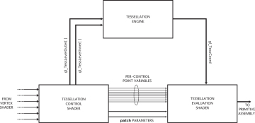
As introduced in the section “Tessellation” in Chapter 3, tessellation is the process of breaking a large primitive referred to as a patch into many smaller primitives before rendering them. There are many uses for tessellation, but the most common application is to add geometric detail to otherwise lower fidelity meshes. In OpenGL, tessellation is produced using three distinct stages of the pipeline — the tessellation control shader (TCS), the fixed-function tessellation engine, and the tessellation evaluation shader (TES). Logically, these three stages fit between the vertex shader and the geometry shader stage. When tessellation is active, incoming vertex data is first processed as normal by the vertex shader and then passed, in groups, to the tessellation control shader.
The tessellation control shader operates on groups of up to 32 vertices1 at a time, collectively known as a patch. In the context of tessellation, the input vertices are often referred to as control points. The tessellation control shader is responsible for generating three things:
- The per-patch inner and outer tessellation factors
- The position and other attributes for each output control point
- Per-patch user-defined varyings
The tessellation factors are sent on to the fixed-function tessellation engine, which uses them to determine the way that it will break up the patch into smaller primitives. Besides the tessellation factors, the output of a tessellation control shader is a new patch (i.e., a new collection of vertices) that is passed to the tessellation evaluation shader after the patch has been tessellated by the tessellation engine. If some of the data is common to all output vertices (such as the color of the patch), then that data may be marked as per patch. When the fixed-function tessellator runs, it generates a new set of vertices spaced across the patch as determined by the tessellation factors and the tessellation mode, which is determined using a layout declaration in the tessellation evaluation shader. The only input to the tessellation evaluation shader generated by OpenGL is a set of coordinates indicating where in the patch the vertex lies. When the tessellator is generating triangles, those coordinates are barycentriccoordinates. When the tessellation engine is generating lines or triangles, those coordinates are simply a pair of normalized values indicating the relative position of the vertex. This is stored in thegl_TessCoord input variable. This setup is shown in the schematic of Figure 8.1.
Tessellation Primitive Modes
The tessellation mode is used to determine how OpenGL breaks up patches into primitives before passing them on to rasterization. This mode is set using an input layout qualifier in the tessellation evaluation shader and may be one of
quads, triangles, or isolines. This primitive mode not only controls the form of the primitives produced by the tessellator, but also the interpretation of thegl_TessCoord input variable in the tessellation evaluation shader.Tessellation Using Quads
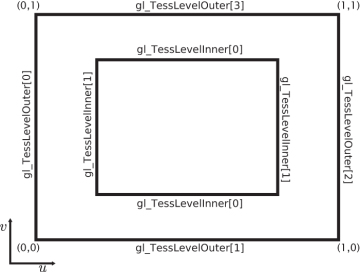
When the chosen tessellation mode is set to quads, the tessellation engine will generate a quadrilateral (or quad) and break it up into a set of triangles. The two elements of the gl_TessLevelInner[] array should be written by the tessellation control shader and control the level of tessellation applied to the innermost region within the quad. The first element sets the tessellation in the horizontal (u) direction, and the second element sets the tessellation level applied in the vertical (v) direction. Also, all four elements of the gl_TessLevelOuter[] array should be written by the tessellation control shader and are used to determine the level of tessellation applied to the outer edges of the quad. This is shown in Figure 8.2.
When the quad is tessellated, the tessellation engine generates vertices across a two-dimensional domain normalized within the quad. The value stored in the gl_TessCoord input variable sent to the tessellation evaluation shader is then a two-dimensional vector (that is, only the x and y components ofgl_TessCoord are valid) containing the normalized coordinate of the vertex within the quad. The tessellation evaluation shader can use these coordinates to generate its outputs from the inputs passed by the tessellation control shader. An example of quad tessellation produced by the tessmodes sample application is shown in Figure 8.3.
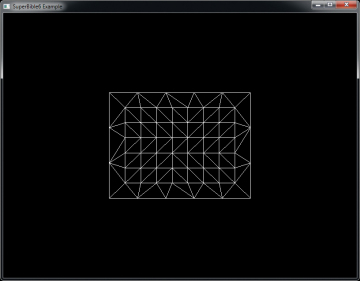
In Figure 8.3, the inner tessellation factors in the u and v directions were set to 9.0 and 7.0, respectively. The outer tessellation factors were set to 3.0 and 5.0 in the u and v directions. This was accomplished using the very simple tessellation control shader shown in Listing 8.1.
Listing 8.1. Simple quad tessellation control shader example
#version430 corelayout(vertices = 4)out;voidmain(void) {if(gl_InvocationID == 0) { gl_TessLevelInner[0] = 9.0; gl_TessLevelInner[1] = 7.0; gl_TessLevelOuter[0] = 3.0; gl_TessLevelOuter[1] = 5.0; gl_TessLevelOuter[2] = 3.0; gl_TessLevelOuter[3] = 5.0; } gl_out[gl_InvocationID].gl_Position = gl_in[gl_InvocationID].gl_Position; }
The result of setting the tessellation factors in this way is visible in Figure 8.3. If you look closely, you will see that along the horizontal outer edges there are five divisions and along the vertical ones there are three divisions. On the interior, you can see that there are 9 divisions along the horizontal axis and 7 along the vertical.
The tessellation evaluation shader that generated Figure 8.3 is shown in Listing 8.2. Notice that the tessellation mode is set using the
quads input layout qualifier near the front of the tessellation evaluation shader. The shader then uses the x and y components of gl_TessCoordinate to perform its own interpolation of the vertex position. In this case, the gl_in[] array is four elements long (as specified in the control shader shown in Listing 8.1).Listing 8.2. Simple quad tessellation evaluation shader example
#version430 corelayout(quads)in;voidmain(void) { // Interpolate along bottom edge using x component of the // tessellation coordinatevec4p1 = mix(gl_in[0].gl_Position, gl_in[1].gl_Position, gl_TessCoord.x); // Interpolate along top edge using x component of the // tessellation coordinatevec4p2 = mix(gl_in[2].gl_Position, gl_in[3].gl_Position, gl_TessCoord.x); // Now interpolate those two results using the y component // of tessellation coordinate gl_Position = mix(p1, p2, gl_TessCoord.y); }
Tessellation Using Triangles
When the tessellation mode is set to triangles (again, using an input layout qualifier in the tessellation control shader), the tessellation engine produces a triangle that is then broken into many smaller triangles. Only the first element of the gl_TessLevelInner[] array is used, and this level is applied to the entirety of the inner area of the tessellated triangle. The first three elements of thegl_TessLevelOuter[] array are used to set the tessellation factors for the three edges of the triangle. This is shown in Figure 8.4.
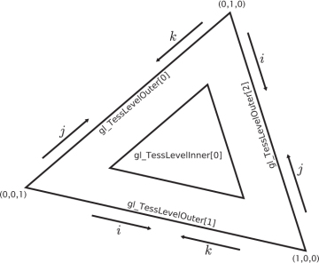
As the tessellation engine generates the vertices corresponding to the tessellated triangles, each vertex is assigned a three-dimensional coordinate called a barycentric coordinate. The three components of a barycentric coordinate can be used to form a weighted sum of three inputs representing the corners of a triangle and arrive at a value that is linearly interpolated across that triangle. An example of triangle tessellation is shown in Figure 8.5.
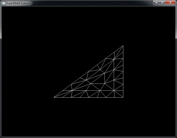
The tessellation control shader used to generate Figure 8.5 is shown in Listing 8.3. Notice how similar it is to Listing 8.1 in that all it does is write constants into the inner and outer tessellation levels and pass through the control point positions unmodified.
Listing 8.3. Simple triangle tessellation control shader example
#version430 corelayout(vertices = 3)out;voidmain(void) {if(gl_InvocationID == 0) { gl_TessLevelInner[0] = 5.0; gl_TessLevelOuter[0] = 8.0; gl_TessLevelOuter[1] = 8.0; gl_TessLevelOuter[2] = 8.0; } gl_out[gl_InvocationID].gl_Position = gl_in[gl_InvocationID].gl_Position; }
Listing 8.3 sets the inner tessellation level to 5.0 and all three outer tessellation levels to 8.0. Again, looking closely at Figure 8.5, you can see that each of the outer edges of the tessellated triangle has 8 divisions and the inner edges have 5 divisions. The tessellation evaluation shader that produced Figure 8.5 is shown in Listing 8.4.
Listing 8.4. Simple triangle tessellation evaluation shader example
#version430 corelayout(triangles)in;voidmain(void) { gl_Position = (gl_TessCoord.x * gl_in[0].gl_Position) + (gl_TessCoord.y * gl_in[1].gl_Position) + (gl_TessCoord.z * gl_in[2].gl_Position); }
Again, to produce a position for each vertex generated by the tessellation engine, we simply calculate a weighted sum of the input vertices. This time, all three components of gl_TessCoord are used and represent the relative weights of the three vertices making up the outermost tessellated triangle. Of course, we’re free to do anything we wish with the barycentric coordinates, the inputs from the tessellation control shader, and any other data we have access to in the evaluation shader.
Tessellation Using Isolines
Isoline tessellation is a mode of the tessellation engine where, rather than producing triangles, it produces real line primitives running along lines of equal v coordinate in the tessellation domain. Each line is broken up into segments along the u direction. The two outer tessellation factors stored in the first two components of gl_TessLevelOuter[] are used to specify the number of lines and the number of segments per line, respectively, and the inner tessellation factors (gl_TessLevelInner[]) are not used at all. This is shown in Figure 8.6.
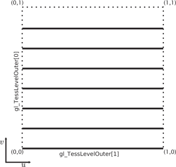
The tessellation control shader shown in Listing 8.5 simply set both the outer tessellation levels to 5.0 and doesn’t write to the inner tessellation levels. The corresponding tessellation evaluation shader is shown in Listing 8.6.
Listing 8.5. Simple isoline tessellation control shader example
#version430 corelayout(vertices = 4)out;voidmain(void) {if(gl_InvocationID == 0) { gl_TessLevelOuter[0] = 5.0; gl_TessLevelOuter[1] = 5.0; } gl_out[gl_InvocationID].gl_Position = gl_in[gl_InvocationID].gl_Position; }
Notice that Listing 8.6 is virtually identical to Listing 8.2 except that the input primitive mode is set to
isolines.Listing 8.6. Simple isoline tessellation evaluation shader example
#version430 corelayout(isolines)in;voidmain(void) { // Interpolate along bottom edge using x component of the // tessellation coordinatevec4p1 = mix(gl_in[0].gl_Position, gl_in[1].gl_Position, gl_TessCoord.x); // Interpolate along top edge using x component of the // tessellation coordinatevec4p2 = mix(gl_in[2].gl_Position, gl_in[3].gl_Position, gl_TessCoord.x); // Now interpolate those two results using the y component // of tessellation coordinate gl_Position = mix(p1, p2, gl_TessCoord.y); }
The result of our extremely simple isoline tessellation example is shown in Figure 8.7.
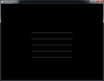
Figure 8.7 doesn’t really seem all that interesting. It’s also difficult to see that each of the horizontal lines is actually made up of several segments.
If, however, we change the tessellation evaluation shader to that shown in Listing 8.7, we can generate the image shown in Figure 8.8.
Listing 8.7. Isoline spirals tessellation evaluation shader
#version430 corelayout(isolines)in;voidmain(void) {floatr = (gl_TessCoord.y + gl_TessCoord.x / gl_TessLevelOuter[0]);floatt = gl_TessCoord.x * 2.0 * 3.14159; gl_Position =vec4(sin(t) * r, cos(t) * r, 0.5, 1.0); }
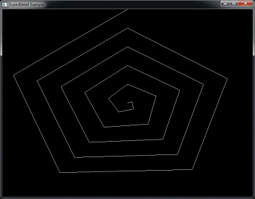
The shader in Listing 8.7 converts the incoming tessellation coordinates into polar form, with the radiusr calculated as smoothly extending from zero to one, and with the angle t as a scaled version of the xcomponent of the tessellation coordinate to produce a single revolution on each isoline. This produces the spiral pattern shown in Figure 8.8, where the segments of the lines are clearly visible.
Tessellation Point Mode
In addition to being able to render tessellated patches using triangles or lines, it’s also possible to render the generated vertices as individual points. This is known as point mode and is enabled using the point_mode input layout qualifier in the tessellation evaluation shader just like any other tessellation mode. When you specify that point mode should be used, the resulting primitives are points. However, this is somewhat orthogonal to the use of the
quads, triangles, or isolines layout qualifiers. That is, you should specify point_mode in addition to one of the other layout qualifiers. Thequads, triangles, and isolines still control the generation of gl_TessCoord and the interpretation of the inner and outer tessellation levels. For example, if the tessellation mode is quads, thengl_TessCoord is a two-dimensional vector, whereas if the tessellation mode is triangles, then it is a three-dimensional barycentric coordinate. Likewise, if the tessellation mode is isolines, only the outer tessellation levels are used, whereas if it is triangles or quads, the inner tessellation levels are used as well.
Figure 8.9 shows a version of Figure 8.5 rendered using point mode next to the original image. To produce the figure on the right, we simply change the input layout qualifier of Listing 8.4 to read:
layout(triangles, point_mode)in;
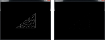
As you can see, the layout of the vertices is identical in both sides of Figure 8.9, but on the right, each vertex has been rendered as a single point.
Tessellation Subdivision Modes
The tessellation engine works by generating a triangle or quad primitive and then subdividing its edges into a number of segments determined by the inner and outer tessellation factors produced by the tessellation control shader. It then groups the generated vertices into points, lines, or triangles and sends them on for further processing. In addition to the type of primitives generated by the tessellation engine, you have quite a bit of control about how it subdivides the edges of the generated primitives.
By default, the tessellation engine will subdivide each edge into a number of equal-sized parts where the number of parts is set by the corresponding tessellation factor. This is known as equal_spacingmode, and although it is the default, it can be made explicit by including the following layout qualifier in your tessellation evaluation shader:
layout(equal_spacing)in;
Equal spacing mode is perhaps the easiest mode to comprehend — simply set the tessellation factor to the number segments you wish to subdivide your patch primitive into along each edge, and the tessellation engine takes care of the rest. Although simple, the equal_spacing mode comes with a significant disadvantage — as you alter the tessellation factor, it is always rounded up to the next nearest integer and will produce a visible jump from one level to the next as the tessellation factor changes. The two other modes alleviate this problem by allowing the segments to be non-equal in length. These modes are fractional_even_spacing and fractional_odd_spacing, and again, you can set these modes by using input layout qualifiers as follows:
layout(fractional_even_spacing)in; // orlayout(fractional_odd_spacing)in;
With fractional even spacing, the tessellation factor is rounded to the next lower even integer and the edge subdivided as if that were the tessellation factor. With fractional odd spacing, the tessellation factor is rounded down to the next lower odd number and the edge subdivided as if that were the tessellation factor. Of course, with either scheme, there is a small remaining segment that doesn’t have the same length as the other segments. That last segment is then cut in half, each half having the same length as the other and is therefore a fractional segment.
Figure 8.10 shows the same triangle tessellated with equal_spacing mode on the left,fractional_even_spacing mode in the center, and fractional_odd_spacing mode on the right.
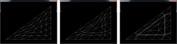
In all three images shown in Figure 8.10, the inner and outer tessellation factors have been set to 5.3. In the leftmost image showing equal_spacing mode, you should be able to see that the number of segments along each of the outer edges of the triangle is 6 — the next integer after 5.3. In the center image, which shows fractional_even_spacing spacing, there are 4 equal-sized segments (as 4 is the next lower even integer to 5.3) and then two additional smaller segments. Finally, in the rightmost image, which demonstrates fractional_odd_spacing, you can see that there are 5 equal-sized segments (5 being the next lower odd integer to 5.3) and there are two very skinny segments that make up the rest.
If the tessellation level is animated, either by being explicitly turned up and down using a uniform, or calculated in the tessellation control shader, the length of the equal-sized segments and the two filler segments will change smoothly and dynamically. Whether you choose fractional_even_spacing orfractional_odd_spacing really depends on which looks better in your application — there is generally no real advantage to either. However, unless you need a guarantee that tessellated edges have equal-sized segments and you can live with popping if the tessellation level changes,fractional_even_spacing or fractional_odd_spacing will generally look better in any dynamic application than equal_spacing.
Controlling the Winding Order
In Chapter 3, “Following the Pipeline,” we introduced culling and explained how the winding order of a primitive affects how OpenGL decides whether to render it. Normally, the winding order of a primitive is determined by the order in which your application presents vertices to OpenGL. However, when tessellation is active, OpenGL generates all the vertices and connectivity information for you. In order to allow you to control the winding order of the resulting primitives, you can specify whether you want the vertices to be generated in clockwise or counterclockwise order. Again, this is specified using an input layout qualifier in the tessellation evaluation shader. To indicate that you want clockwise winding order, use the following layout qualifier:
layout(cw)in;
To specify that the winding order of the primitives generated by the tessellation engine be counterclockwise, include
layout(ccw)in;
The cw and ccw layout qualifiers can be combined with the other input layout qualifiers specified in the tessellation control shader. By default, the winding order is counterclockwise, and so you can omit this layout qualifier if that is what you need. Also, it should be self-evident that winding order only applies to triangles, and so if your application generates isolines or points, then the winding order is ignored — your shader can still include the winding order layout qualifier, but it won’t be used.
Passing Data between Tessellation Shaders
In this section, we have looked at how to set the inner and outer tessellation levels for the quad, triangle, and point primitive modes. However, the resulting images in Figures 8.3 through 8.8 aren’t particularly exciting, in part because we haven’t done anything but compute the positions of the resulting vertices and then just shaded the resulting primitives solid white. In fact, we have rendered all of these images using lines by setting the polygon mode to GL_LINE with the glPolygonMode()function. To produce something a little more interesting, we’re going to need to pass more data along the pipeline.
Before a tessellation control shader is run, each vertex represents a control point, and the vertex shader runs once for each input control point and produces its output as normal. The vertices (or control points) are then grouped together and passed together to the tessellation control shader.
The tessellation control shader processes this group of control points and produces a new group of control points that may or may not have the same number of elements in it as the original group. The tessellation control shader actually runs once for each control point in the output group, but each invocation of the tessellation control shader has access to all of the input control points. For this reason, both the inputs to and outputs from a tessellation control shader are represented as arrays. The input arrays are sized by the number of control points in each patch, which is set by calling
glPatchParameteri(GL_PATCH_VERTICES, n);
Here, n is the number of vertices per patch. By default, the number of vertices per patch is 3. The size of the input arrays in the tessellation control shader is set by this parameter, and their contents come from the vertex shader. The built-in variable gl_in[] is always available and is declared as an array of the gl_PerVertex structure. This structure is where the built-in outputs go after you write to them in your vertex shader. All other outputs from the vertex shader become arrays in the tessellation control shader as well. In particular, if you use an output block in your vertex shader, the instance of that block becomes an array of instances in the tessellation control shader. So, for example
outVS_OUT {vec4foo;vec3bar;intbaz } vs_out;
becomes
inVS_OUT {vec4foo;vec3bar;intbaz; } tcs_in[];
in the tessellation evaluation shader.
The output of the tessellation control shader is also an array, but its size is set by the vertices output layout qualifier at the front of the shader. It is quite common to set the input and output vertex count to the same value (as was the case in the samples earlier in this section) and then pass the input directly to the output from the tessellation control shader. However, there’s no requirement for this, and the size of the output arrays in the tessellation control shader is limited by the value of theGL_MAX_PATCH_VERTICES constant.
As the outputs of the tessellation control shader are arrays, so the inputs to the tessellation evaluation shader are also similarly sized arrays. The tessellation evaluation shader runs once per generated vertex and, like the tessellation control shader, has access to all of the data for all of the vertices in the patch.
In addition to the per-vertex data passed from tessellation control shader to the tessellation evaluation shader in arrays, it’s also possible to pass data directly between the stages that is constant across an entire patch. To do this, simply declare the output variable in the tessellation control shader and the corresponding input in the tessellation evaluation shader using the
patch keyword. In this case the variable does not have to be declared as an array (although you are welcome to use arrays as patchqualified variables) as there is only one instance per patch.Rendering without a Tessellation Control Shader
The purpose of the tessellation control shader is to perform tasks such as computing the value of per-patch inputs to the tessellation evaluation shader and to calculate the values of the inner and outer tessellation levels that will be used by the fixed-function tessellator. However, in some simple applications, there are no per-patch inputs to the tessellation evaluation shader, and the tessellation control shader only writes constants to the tessellation levels. In this case, it’s actually possible to set up a program with a tessellation evaluation shader, but without a tessellation control shader.
When no tessellation control shader is present, the default values of all inner and outer tessellation levels is 1.0. You can change this by calling glPatchParameterfv(), whose prototype is
voidglPatchParameterfv(GLenum pname,constGLfloat * values);
If pname is GL_PATCH_DEFAULT_INNER_LEVEL, then values should point to an array of two floating-point values that will be used as the new default inner tessellation levels in the absence of a tessellation control shader. Likewise, if pname is GL_PATCH_DEFAULT_OUTER_LEVEL, then valuesshould point to an array of four floating-point values that will be used as the new default outer tessellation levels.
If no tessellation control shader is part of the current pipeline, then the number of control points that is presented to the tessellation evaluation shader is the same as the number of control points per patch set by the glPatchParameteri() when the pname parameter is set to GL_PATCH_VERTICES. In this case, the input to the tessellation evaluation shader comes directly from the vertex shader. That is, the input to the tessellation evaluation shader is an array formed from the outputs of the vertex shader invocations that generated the patch.
Communication between Shader Invocations
Although the purpose of output variables in tessellation control shaders is primarily to pass data to the tessellation evaluation shader, they also have a secondary purpose. That is, to communicate data between control shader invocations. As you have read, the tessellation control shader runs a single invocation for each output control point in a patch. Each output variable in the tessellation control shader is therefore an array, the length of which is the number of control points in the output patch. Normally, each tessellation control shader invocation will take responsibility for writing to one element of this array.
What might not be obvious is that tessellation control shaders can actually read from their output variables — including those that might be written by other invocations! Now, the tessellation control shader is designed in such a way that the invocations can run in parallel. However, there is no ordering guarantee over how those shaders actually execute your code. That means that you have no idea if, when you read from another invocation’s output variable, that that invocation has actually written data there.
To deal with this, GLSL includes the barrier() function. This is known as a flow-control barrier, as it enforces relative order to the execution of multiple shader invocations. The barrier() function really shines when used in compute shaders — we’ll get to that later. However, it’s available in a limited form in tessellation control shaders, too, with a number of restrictions. In particular, in a tessellation control shader, barrier() may only be called directly from within your main() function, and can’t be inside any control flow structures (such as
if, else, while, or switch).
When you call barrier(), the tessellation control shader invocation will stop and wait for all the other invocations in the same patch to catch up. It won’t continue execution until all the other invocations have reached the same point. This means that if you write to an output variable in a tessellation control shader and then call barrier(), you can be sure that all the other invocations have done the same thing by the time barrier() returns, and therefore it’s safe to go ahead and read from the other invocations’ output variables.
Tessellation Example — Terrain Rendering
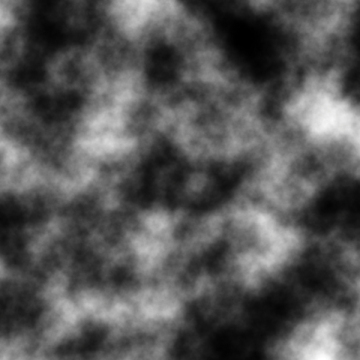
To demonstrate a potential use for tessellation, we will cover a simple terrain rendering system based on quadrilateral patches and displacement mapping. The code for this example is part of the dispmapsample. A displacement map is a texture that contains the displacement from a surface at each location. Each patch represents a small region of a landscape that is tessellated depending on its likely screen-space area. Each tessellated vertex is moved along the tangent to the surface by the value stored in the displacement map. This adds geometric detail to the surface without needing to explicitly store the positions of each tessellated vertex. Rather, only the displacements from an otherwise flat landscape are stored in the displacement map and are applied at runtime in the tessellation evaluation shader. The displacement map (which is also known as a height map) used in the example is shown in Figure 8.11.
Our first step is to set up a simple vertex shader. As each patch is effectively a simple quad, we can use constants in the shader to represent the four vertices rather than setting up vertex arrays for it. The complete shader is shown in Listing 8.8. The shader uses the instance number (stored ingl_InstanceID) to calculate an offset for the patch, which is a one-unit square in the xz plane, centered on the origin. In this application, we will render a grid of 64 × 64 patches, and so the x and yoffsets for the patch are calculated by taking gl_InstanceID modulo 64 and gl_InstanceID divided by 64. The vertex shader also calculates the texture coordinates for the patch, which are passed to the tessellation control shader in vs_out.tc.
Listing 8.8. Vertex shader for terrain rendering
#version430 coreoutVS_OUT {vec2tc; } vs_out;voidmain(void) {const vec4vertices[] =vec4[](vec4(-0.5, 0.0, -0.5, 1.0),vec4( 0.5, 0.0, -0.5, 1.0),vec4(-0.5, 0.0, 0.5, 1.0),vec4( 0.5, 0.0, 0.5, 1.0));intx = gl_InstanceID & 63;inty = gl_InstanceID >> 6;vec2offs =vec2(x, y); vs_out.tc = (vertices[gl_VertexID].xz + offs +vec2(0.5)) / 64.0; gl_Position = vertices[gl_VertexID] +vec4(float(x - 32), 0.0,float(y - 32), 0.0); }
Next, we come to the tessellation control shader. Again, the complete shader is shown in Listing 8.9. In this example, the bulk of the rendering algorithm is implemented in the tessellation control shader, and the majority of the code is only executed by the first invocation. Once we have determined that we are the first invocation by checking that gl_InvocationID is zero, we calculate the tessellation levels for the whole patch. First, we project the corners of the patch into normalized device coordinates by multiplying the incoming coordinates by the model-view-projection matrix and then dividing each of the four points by their own homogeneous .w component.
Next, we calculate the length of each of the four edges of the patch in normalized device space after projecting them onto the xy plane by ignoring their z components. Then, the shader calculates the tessellation levels of each edge of the patch as a function of its length using a simple scale and bias. Finally, the inner tessellation factors are simply set to the minimum of the outer tessellation factors calculated from the edge lengths in the horizontal or vertical directions.
You may also have noticed a piece of code in Listing 8.9 that checks whether all of the z coordinates of the projected control points are less than zero and then sets the outer tessellation levels to zero if this happens. This is an optimization that culls entire patches that are behind2 the viewer.
Listing 8.9. Tessellation control shader for terrain rendering
#version430 corelayout(vertices = 4)out;inVS_OUT {vec2tc; } tcs_in[];outTCS_OUT {vec2tc; } tcs_out[];uniform mat4mvp;voidmain(void) {if(gl_InvocationID == 0) {vec4p0 = mvp * gl_in[0].gl_Position;vec4p1 = mvp * gl_in[1].gl_Position;vec4p2 = mvp * gl_in[2].gl_Position;vec4p3 = mvp * gl_in[3].gl_Position; p0 /= p0.w; p1 /= p1.w; p2 /= p2.w; p3 /= p3.w;if(p0.z <= 0.0 || p1.z <= 0.0 || p2.z <= 0.0 || p3.z <= 0.0) { gl_TessLevelOuter[0] = 0.0; gl_TessLevelOuter[1] = 0.0; gl_TessLevelOuter[2] = 0.0; gl_TessLevelOuter[3] = 0.0; }else{floatl0 = length(p2.xy - p0.xy) * 16.0 + 1.0;floatl1 = length(p3.xy - p2.xy) * 16.0 + 1.0;floatl2 = length(p3.xy - p1.xy) * 16.0 + 1.0;floatl3 = length(p1.xy - p0.xy) * 16.0 + 1.0; gl_TessLevelOuter[0] = l0; gl_TessLevelOuter[1] = l1; gl_TessLevelOuter[2] = l2; gl_TessLevelOuter[3] = l3; gl_TessLevelInner[0] = min(l1, l3); gl_TessLevelInner[1] = min(l0, l2); } } gl_out[gl_InvocationID].gl_Position = gl_in[gl_InvocationID].gl_Position; tcs_out[gl_InvocationID].tc = tcs_in[gl_InvocationID].tc; }
Once the tessellation control shader has calculated the tessellation levels for the patch, it simply copies its input to its output. It does this per instance and passes the resulting data to the tessellation evaluation shader, which is shown in Listing 8.10.
Listing 8.10. Tessellation evaluation shader for terrain rendering
#version430 corelayout(quads, fractional_odd_spacing)in;uniform sampler2Dtex_displacement;uniform mat4mvp;uniform floatdmap_depth;inTCS_OUT {vec2tc; } tes_in[];outTES_OUT {vec2tc; } tes_out;voidmain(void) {vec2tc1 = mix(tes_in[0].tc, tes_in[1].tc, gl_TessCoord.x);vec2tc2 = mix(tes_in[2].tc, tes_in[3].tc, gl_TessCoord.x);vec2tc = mix(tc2, tc1, gl_TessCoord.y);vec4p1 = mix(gl_in[0].gl_Position, gl_in[1].gl_Position, gl_TessCoord.x);vec4p2 = mix(gl_in[2].gl_Position, gl_in[3].gl_Position, gl_TessCoord.x);vec4p = mix(p2, p1, gl_TessCoord.y); p.y += texture(tex_displacement, tc).r * dmap_depth; gl_Position = mvp * p; tes_out.tc = tc; }
The tessellation evaluation shader shown in Listing 8.10 first calculates the texture coordinate of the generated vertex by linearly interpolating the texture coordinates passed from the tessellation control shader of Listing 8.9 (which were in turn generated by the vertex shader of Listing 8.8). It then applies a similar interpolation to the incoming control point positions to produce the position of the outgoing vertex. However, once it’s done that, it uses the texture coordinate that it calculated to offset the vertex in the y direction before multiplying that result by the model-view-projection matrix (the same one that was used in the tessellation control shader). It also passes the computed texture coordinate on to the fragment shader in tes_out.tc. That fragment shader is shown in Listing 8.11.
Listing 8.11. Fragment shader for terrain rendering
#version430 coreout vec4color;layout(binding= 1)uniform sampler2Dtex_color;inTES_OUT {vec2tc; } fs_in;voidmain(void) { color = texture(tex_color, fs_in.tc); }
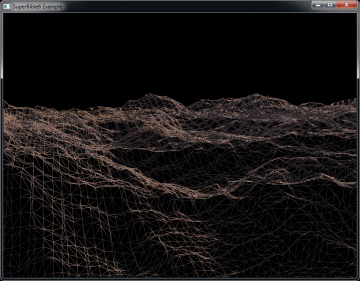
The fragment shader shown in Listing 8.11 is really pretty simple. All it does is use the texture coordinate that the tessellation evaluation shader gave it to look up a color for the fragment. The result of rendering with this set of shaders is shown in Figure 8.12.
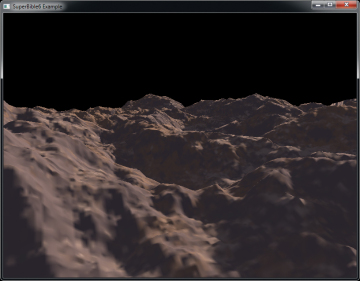
Of course, if we’ve done our job correctly, you shouldn’t be able to tell that the underlying geometry is tessellated. However, if you look at the wireframe version of the image shown in Figure 8.13, you can clearly see the underlying triangular mesh of the landscape. The goals of the program are that all of the triangles rendered on the screen have roughly similar screen-space area and that sharp transitions in the level of tessellation are not visible in the rendered image.
Tessellation Example — Cubic Bézier Patches
In the displacement mapping example, all we did was use a (very large) texture to drive displacement from a flat surface and then use tessellation to increase the number of polygons in the scene. This is a type of brute force, data driven approach to geometric complexity. In the cubicbezier example described here, we will use math to drive geometry — we’re going to render a cubic Bézier patch. If you look back to Chapter 4, you’ll see that we’ve covered all the number crunching we’ll need here.
A cubic Bézier patch is a type of higher order surface and is defined by a number of control points3 that provide input to a number of interpolation functions that define the surface’s shape. A Bézier patch has 16 control points, laid out in a 4 × 4 grid. Very often (including in this example), they are equally spaced in two dimensions varying only in distance from a shared plane. However, they don’t have to be. Free-form Bézier patches are extremely powerful modeling tools, being used natively by many pieces of modeling and design software. With OpenGL tessellation, it’s possible to render them directly.
The simplest method of rendering a Bézier patch is to treat the four control points in each row of the patch as the control points for a single cubic Bézier curve, just as was described in Chapter 4. Given our 4 × 4 grid of control points, we have 4 curves, and if we interpolate along each of them using the same value of t, we will end up with 4 new points. We use these 4 points as the control points for a second cubic Bézier curve. Interpolating along this second curve using a new value for t gives us a second point that lies on the patch. The two values of t (let’s call them t0 and t1) are the domain of the patch and are what is handed to us in the tessellation evaluation shader in gl_TessCoord.xy.
In this example, we’ll perform tessellation in view space. That means that in our vertex shader, we’ll transform our patch’s control points into view space by multiplying their coordinates by the model-view matrix — that is all. This simple vertex shader is shown in Listing 8.12.
Listing 8.12. Cubic Bézier patch vertex shader
#version430 corein vec4position;uniform mat4mv_matrix;voidmain(void) { gl_Position = mv_matrix * position; }
Once our control points are in view space, they are passed to our tessellation control shader. In a more advanced4 algorithm, we could project the control points into screen space, determine the length of the curve, and set the tessellation factors appropriately. However, in this example, we’ll settle with a simple fixed tessellation factor. As in previous examples, we set the tessellation factors only whengl_InvocationID is zero, but pass all of the other data through once per invocation. The tessellation control shader is shown in Listing 8.13.
Listing 8.13. Cubic Bézier patch tessellation control shader
#version430 corelayout(vertices = 16)out;voidmain(void) {if(gl_InvocationID == 0) { gl_TessLevelInner[0] = 16.0; gl_TessLevelInner[1] = 16.0; gl_TessLevelOuter[0] = 16.0; gl_TessLevelOuter[1] = 16.0; gl_TessLevelOuter[2] = 16.0; gl_TessLevelOuter[3] = 16.0; } gl_out[gl_InvocationID].gl_Position = gl_in[gl_InvocationID].gl_Position; }
Next, we come to the tessellation evaluation shader. This is where the meat of the algorithm lies. The shader in its entirety is shown in Listing 8.14. You should recognize the cubic_bezier andquadratic_bezier functions from Chapter 4. The evaluate_patch function is responsible for evaluating5 the vertex’s coordinate given the input patch coordinates and the vertex’s position within the patch.
Listing 8.14. Cubic Bézier patch tessellation evaluation shader
#version430 corelayout(quads, equal_spacing, cw)in;uniform mat4mv_matrix;uniform mat4proj_matrix;outTES_OUT {vec3N; } tes_out;vec4quadratic_bezier(vec4A,vec4B,vec4C,floatt) {vec4D = mix(A, B, t);vec4E = mix(B, C, t);returnmix(D, E, t); }vec4cubic_bezier(vec4A,vec4B,vec4C,vec4D,floatt) {vec4E = mix(A, B, t);vec4F = mix(B, C, t);vec4G = mix(C, D, t);returnquadratic_bezier(E, F, G, t); }vec4evaluate_patch(vec2at) {vec4P[4];inti;for(i = 0; i < 4; i++) { P[i] = cubic_bezier(gl_in[i + 0].gl_Position, gl_in[i + 4].gl_Position, gl_in[i + 8].gl_Position, gl_in[i + 12].gl_Position, at.y); }returncubic_bezier(P[0], P[1], P[2], P[3], at.x); }const floatepsilon = 0.001;voidmain(void) {vec4p1 = evaluate_patch(gl_TessCoord.xy);vec4p2 = evaluate_patch(gl_TessCoord.xy +vec2(0.0, epsilon));vec4p3 = evaluate_patch(gl_TessCoord.xy +vec2(epsilon, 0.0));vec3v1 = normalize(p2.xyz - p1.xyz);vec3v2 = normalize(p3.xyz - p1.xyz); tes_out.N = cross(v1, v2); gl_Position = proj_matrix * p1; }
In our tessellation evaluation shader, we calculate the surface normal to the patch by evaluating the patch position at two points very close to the point under consideration, using the additional points to calculate two vectors that lie on the patch and then taking their cross product. This is passed to the fragment shader shown in Listing 8.15.
Listing 8.15. Cubic Bézier patch fragment shader
#version430 coreout vec4color;inTES_OUT {vec3N; } fs_in;voidmain(void) {vec3N = normalize(fs_in.N);vec4c =vec4(1.0, -1.0, 0.0, 0.0) * N.z +vec4(0.0, 0.0, 0.0, 1.0); color = clamp(c,vec4(0.0),vec4(1.0)); }
This fragment shader performs a very simple lighting calculation using the z component of the surface normal. The result of rendering with this shader is shown in Figure 8.14.
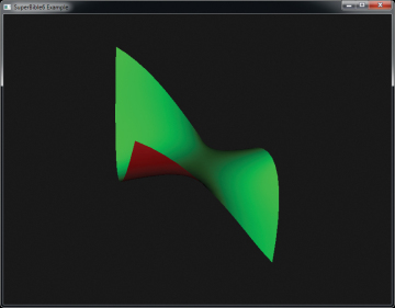
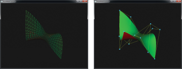
Because the rendered patch shown in Figure 8.14 is smooth, it is hard to see the tessellation that has been applied to the shape. The left of Figure 8.15 shows a wireframe representation of the tessellated patch, and the right side of Figure 8.15 shows the patch’s control points and the control cage, which is formed by creating a grid of lines between the control points.
No comments:
Post a Comment