1. "Shadow Mapping, learnopengl"
...
Shadow Mapping
Shadows are a result of the absence of light due to occlusion; when a light source's light rays do not hit an object because it gets occluded by some other object the object is in shadow. Shadows add a great deal of realism to a lighted scene and make it easier for a viewer to observe spatial relationships between objects. They give a greater sense of depth to our scene and objects. For example, take a look at the following image of a scene with and without shadows:
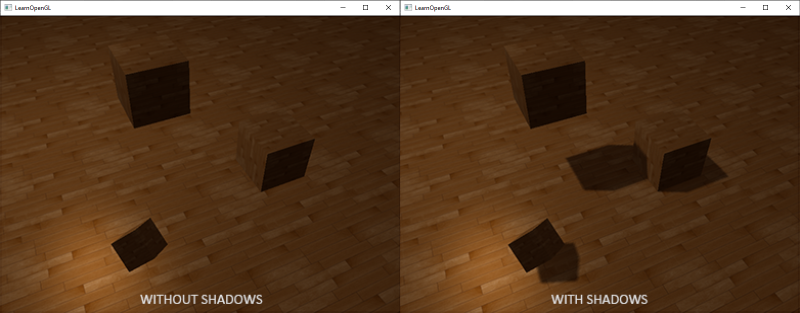
You can see that with shadows it becomes much more obvious how the objects relate to each other. For instance, the fact that one of the cubes is floating above the others is much more noticeable when we have shadows.
Shadows are a bit tricky to implement though, specifically because in current real-time research a perfect shadow algorithm hasn't been developed yet. There are several good shadow approximation techniques, but they all have their little quirks and annoyances which we have to take into account.
One technique used by most videogames that gives decent results and is relatively easy to implement is shadow mapping . Shadow mapping is not too difficult to understand, doesn't cost too much in performance and is quite easily extended into more advanced algorithms (like Omnidirectional Shadow Maps and Cascaded Shadow Maps).
Shadow mapping
The idea behind shadow mapping is quite simple: we render the scene from the light's point of view and everything we see from the light's perspective is lit and everything we can't see must be in shadow. Imagine a floor section with a large box between itself and a light source. Since the light source will see this box and not the floor section when looking in its direction that specific floor section should be in shadow.
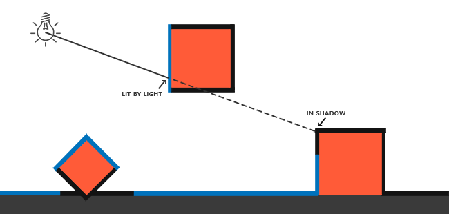
Here all the blue lines represent the fragments that the light source can see. The occluded fragments are shown as black lines: these are rendered as being shadowed. If we were to draw a line or ray from the light source to a fragment on the right-most box we can see the ray first hits the floating container before hitting the right-most container. As a result, the floating container's fragment is lit and the right-most container's fragment is not lit and thus in shadow.
- We want to get a point on the ray where it first hit an object and compare this closest point to other points on this ray.
- We then do a basic test to see if a test point's ray position is further down the ray than the closest point and if so, the test point must be in shadow.
- Iterating through possibly thousands of light rays from such a light source is an extremely inefficient approach and doesn't lend itself too well for real-time rendering.
- We can do something similar, but without casting light rays. Instead, we use something we're quite familiar with: the depth buffer.
- You probably remember from the depth testing tutorial that a value in the depth buffer corresponds to the depth of a fragment clamped to [0,1] from the camera's point of view.
- What if we were to render the scene from the light's perspective and store the resulting depth values in a texture? This way we can sample the closest depth values as seen from the light's perspective.
- After all, the depth values show the first fragment visible from the light's perspective. We store all these depth values in a texture that we call a
depth map orshadow map .
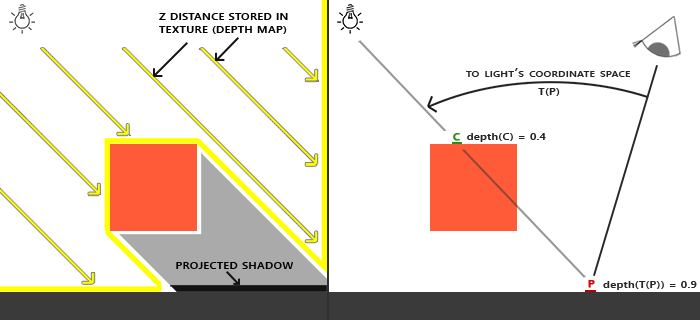
- The left image shows a directional light source (all light rays are parallel) casting a shadow on the surface below the cube.
- Using the depth values stored in the depth map we find the closest point and use that to determine whether fragments are in shadow.
- We create the depth map by rendering the scene (from the light's perspective) using a view and projection matrix specific to that light source.
- This projection and view matrix together form a transformation T that transforms any 3D position to the light's visible coordinate space.
In the right image we see the same directional light and the viewer.
....
Shadow mapping consists of two passes:
- first we render the depth map
- the second pass we render the scene as normal and use the generated depth map to calculate whether fragments are in shadow.
- It might sound a bit complicated, but as soon as we walk through the technique step-by-step it'll likely start to make sense.
The depth map
The first pass requires us to generate a depth map. The depth map is the depth texture as rendered from the light's perspective that we'll be using for calculating shadows. Because we need to store the rendered result of a scene into a texture we're going to need framebuffers again.
First we'll create a framebuffer object for rendering the depth map:
GLuint depthMapFBO;
glGenFramebuffers (1, &depthMapFBO);
Next we create a 2D texture that we'll use as the framebuffer's depth buffer:
const GLuint SHADOW_WIDTH = 1024, SHADOW_HEIGHT = 1024;
GLuint depthMap;
glGenTextures (1, &depthMap);
glBindTexture (GL_TEXTURE_2D, depthMap);
glTexImage2D (GL_TEXTURE_2D, 0, GL_DEPTH_COMPONENT,
SHADOW_WIDTH, SHADOW_HEIGHT, 0, GL_DEPTH_COMPONENT, GL_FLOAT, NULL);
glTexParameter i(GL_TEXTURE_2D, GL_TEXTURE_MIN_FILTER, GL_NEAREST);
glTexParameter i(GL_TEXTURE_2D, GL_TEXTURE_MAG_FILTER, GL_NEAREST);
glTexParameter i(GL_TEXTURE_2D, GL_TEXTURE_WRAP_S, GL_REPEAT);
glTexParameter i(GL_TEXTURE_2D, GL_TEXTURE_WRAP_T, GL_REPEAT);
Generating the depth map shouldn't look too complicated. Because we only care about depth values we specify the texture's formats as GL_DEPTH_COMPONENT. We also give the texture a width and height of
1024: this is the resolution of the depth map.
With the generated depth texture we can attach it as the framebuffer's depth buffer:
glBindFramebuffer (GL_FRAMEBUFFER, depthMapFBO);
glFramebufferTexture2D (GL_FRAMEBUFFER, GL_DEPTH_ATTACHMENT, GL_TEXTURE_2D, depthMap, 0);
glDrawBuffer(GL_NONE);
glReadBuffer(GL_NONE);
glBindFramebuffer (GL_FRAMEBUFFER, 0);
We only need the depth information when rendering the scene from the light's perspective so there is no need for a color buffer. A framebuffer object however is not complete without a color buffer so we need to explicitly tell OpenGL we're not going to render any color data. We do this by setting both the read and draw buffer to GL_NONE with glDrawBuffer andglReadbuffer .
With a properly configured framebuffer that renders depth values to a texture we can start the first pass: generating the depth map. The complete rendering stage of both passes will looks a bit like this:
// 1. first render to depth map
glViewport (0, 0, SHADOW_WIDTH, SHADOW_HEIGHT);
glBindFramebuffer (GL_FRAMEBUFFER, depthMapFBO);
glClear (GL_DEPTH_BUFFER_BIT);
ConfigureShaderAndMatrices();
RenderScene();
glBindFramebuffer (GL_FRAMEBUFFER, 0);
// 2. then render scene as normal with shadow mapping (using depth map)
glViewport (0, 0, SCR_WIDTH, SCR_HEIGHT);
glClear (GL_COLOR_BUFFER_BIT | GL_DEPTH_BUFFER_BIT);
ConfigureShaderAndMatrices();
glBindTexture (GL_TEXTURE_2D, depthMap);
RenderScene();
This code left out some details, but it'll give you the general idea of shadow mapping. What is important to note here are the calls to glViewport
Light space transform
An unknown in the previous snippet of code is the ConfigureShaderAndMatrices function. In the second pass this is business as usual: make sure proper projection and view matrices are set and the relevant model matrices per object. However, in the first pass we use a different projection and view matrix to render the scene from the light's point of view.
Because we're modelling a directional light source all its light rays are parallel. For this reason we're going to use an orthographic projection matrix for the light source where there is no perspective deform:
GLfloat near_plane = 1.0f, far_plane = 7.5f;
glm::mat4 lightProjection = glm::ortho (-10.0f, 10.0f, -10.0f, 10.0f, near_plane, far_plane);
Here is an example orthographic projection matrix as used in this tutorial's demo scene. Because a projection matrix indirectly determines the range of what is visible e.g. what is not clipped you want to make sure the size of the projection frustum correctly contains the objects you want to be in the depth map. When objects or fragments are not in the depth map they will not produce shadows.
To create a view matrix to transform each object so they're visible from the light's point of view we're going to use the infamous glm::lookAt
glm::mat4 lightView = glm::lookAt (glm::vec3(-2.0f, 4.0f, -1.0f),
glm::vec3( 0.0f, 0.0f, 0.0f),
glm::vec3( 0.0f, 1.0f, 0.0f));
Combining these two gives us a light space transformation matrix that transforms each world-space vector into the space as visible from the light source; exactly what we need to render the depth map.
glm::mat4 lightSpaceMatrix = lightProjection * lightView;
This lightSpaceMatrix is the transformation matrix that we earlier denoted as . With this lightSpaceMatrix we can render the scene as usual as long as we give the shader the light-space equivalents of the projection and view matrices. However, we only care about depth values and not all the expensive fragment calculations in our main shader. To save performance we're going to use a different, but much simpler shader for rendering to the depth map.
Render to depth map
When we render the scene from the light's perspective we'd much rather use a simple shader that only transforms the vertices to light space and not much more. For such a simple shader called simpleDepthShader we'll use the following vertex shader:
#version 330 core
layout (location = 0) in vec3 position;

uniform mat4 lightSpaceMatrix;
uniform mat4 model;

void main()
{
    gl_Position = lightSpaceMatrix * model * vec4(position, 1.0f);
}
This vertex shader takes a per-object model, a vertex and transforms all vertices to light space using lightSpaceMatrix.
Since we have no color buffer the resulting fragments do not require any processing, so we can simply use an empty fragment shader:
#version 330 core

void main()
{
    // gl_FragDepth = gl_FragCoord.z;
}
The empty fragment shader does no processing whatsoever and at the end of its run the depth buffer is updated. We could explicitly set the depth by uncommenting its one line, but this is effectively what happens behind the scene anyways.
Rendering the depth buffer now effectively becomes:
simpleDepthShader.Use();
glUniform Matrix4fv(lightSpaceMatrixLocation, 1, GL_FALSE, glm::value_ptr(lightSpaceMatrix));
glViewport (0, 0, SHADOW_WIDTH, SHADOW_HEIGHT);
glBindFramebuffer (GL_FRAMEBUFFER, depthMapFBO);
glClear (GL_DEPTH_BUFFER_BIT);
RenderScene(simpleDepthShader);
glBindFramebuffer (GL_FRAMEBUFFER, 0);
Here the RenderScene function takes a shader program, calls all relevant drawing functions and sets the corresponding model matrices where necessary.
The result is a nicely filled depth buffer holding the closest depth of each visible fragment from the light's perspective. By projecting this texture onto a 2D quad that fills the screen (similar to what we did in the post-processing section at the end of the framebuffers tutorial) we get something like this:
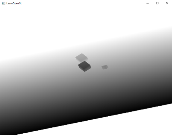
For rendering the depth map onto a quad we used the following fragment shader:
#version 330 core
out vec4 color;
in vec2 TexCoords;

uniform sampler2D depthMap;

void main()
{
    float depthValue = texture(depthMap, TexCoords).r;
    color = vec4(vec3(depthValue), 1.0);
}
Note that there are some subtle changes when displaying depth using a perspective projection matrix instead of an orthographic projection matrix as depth is non-linear when using perspective projection. At the end of this tutorial we'll discuss some of these subtle differences.
You can find the source code for rendering a scene to a depth map here.
Rendering shadows
With a properly generated depth map we can start generating the actual shadows. The code to check if a fragment is in shadow is (quite obviously) executed in the fragment shader, but we do the light-space transformation in the vertex shader:
#version 330 core
layout (location = 0) in vec3 position;
layout (location = 1) in vec3 normal;
layout (location = 2) in vec2 texCoords;

out VS_OUT {
    vec3 FragPos;
    vec3 Normal;
    vec2 TexCoords;
    vec4 FragPosLightSpace;
} vs_out;

uniform mat4 projection;
uniform mat4 view;
uniform mat4 model;
uniform mat4 lightSpaceMatrix;

void main()
{
    gl_Position = projection * view * model * vec4(position, 1.0f);
    vs_out.FragPos = vec3(model * vec4(position, 1.0));
    vs_out.Normal = transpose(inverse(mat3(model))) * normal;
    vs_out.TexCoords = texCoords;
    vs_out.FragPosLightSpace = lightSpaceMatrix * vec4(vs_out.FragPos, 1.0);
}
What is new here is the extra output vector FragPosLightSpace. We take the same lightSpaceMatrix (used to transform vertices to light space in the depth map stage) and transform the world-space vertex position to light space. The vertex shader passes a normally transformed world-space vertex position vs_out.FragPos and a light-space transformedvs_out.FragPosLightSpace to the fragment shader.
The fragment shader we'll use to render the scene uses the Blinn-Phong lighting model. Within the fragment shader we then calculate a shadow value that is either
1.0 when the fragment is in shadow or 0.0 when not in shadow. The resultingdiffuse and specular colors are then multiplied by this shadow component. Because shadows are rarely completely dark due to light scattering we leave the ambient color out of the shadow multiplications.
#version 330 core
out vec4 FragColor;

in VS_OUT {
    vec3 FragPos;
    vec3 Normal;
    vec2 TexCoords;
    vec4 FragPosLightSpace;
} fs_in;

uniform sampler2D diffuseTexture;
uniform sampler2D shadowMap;

uniform vec3 lightPos;
uniform vec3 viewPos;

float ShadowCalculation(vec4 fragPosLightSpace)
{
    [...]
}

void main()
{
    vec3 color = texture(diffuseTexture, fs_in.TexCoords).rgb;
    vec3 normal = normalize(fs_in.Normal);
    vec3 lightColor = vec3(1.0);
    // Ambient
    vec3 ambient = 0.15 * color;
    // Diffuse
    vec3 lightDir = normalize(lightPos - fs_in.FragPos);
    float diff = max(dot(lightDir, normal), 0.0);
    vec3 diffuse = diff * lightColor;
    // Specular
    vec3 viewDir = normalize(viewPos - fs_in.FragPos);
    float spec = 0.0;
    vec3 halfwayDir = normalize(lightDir + viewDir);
    spec = pow(max(dot(normal, halfwayDir), 0.0), 64.0);
    vec3 specular = spec * lightColor;
    // Calculate shadow
    float shadow = ShadowCalculation(fs_in.FragPosLightSpace);
    vec3 lighting = (ambient + (1.0 - shadow) * (diffuse + specular)) * color;

    FragColor = vec4(lighting, 1.0f);
}
The fragment shader is largely a copy of what we used in the advanced lighting tutorial, but with an added shadow calculation. We declared a function ShadowCalculation that does most of the shadow work. At the end of the fragment shader we multiply the diffuse and specular contributions by the inverse of the shadow component e.g. how much the fragment is not in shadow. This fragment shader takes as extra input the light-space fragment position and the depth map generated from the first render pass.
The first thing to do to check whether a fragment is in shadow is transform the light-space fragment position in clip-space to normalized device coordinates. When we output a clip-space vertex position to gl_Position in the vertex shader, OpenGL automatically does a perspective divide e.g. transform clip-space coordinates in the range [
-w,w] to [-1,1] by dividing the x, yand z component by the vector's w component. As the clip-space FragPosLightSpace is not passed to the fragment shader via gl_Position we have to do this perspective divide ourselves:
float ShadowCalculation(vec4 fragPosLightSpace)
{
    // perform perspective divide
    vec3 projCoords = fragPosLightSpace.xyz / fragPosLightSpace.w;
    [...]
}
This returns the fragment's light-space position in the range [
-1,1].w component of a vertex remains untouched so this step is actually quite meaningless. However, it is necessary when using perspective projection so keeping this line ensures it works with both projection matrices.
Because the depth from the depth map is in the range [
0,1] and we also want to use projCoords to sample from the depth map so we transform the NDC coordinates to the range [0,1]:
projCoords = projCoords * 0.5 + 0.5;
With these projected coordinates we can sample the depth map as the resulting [
0,1] coordinates from projCoordsdirectly correspond to the transformed NDC coordinates from the first render pass. This gives us the closest depth from the light's point of view:
float closestDepth = texture(shadowMap, projCoords.xy).r;
To get the current depth at the fragment we simply retrieve the projected vector's
z coordinate which equals the depth of the fragment from the light's perspective.
float currentDepth = projCoords.z;
The actual comparison is then simply a check whether currentDepth is higher than closestDepth and if so, the fragment is in shadow.
float shadow = currentDepth > closestDepth ? 1.0 : 0.0;
The complete ShadowCalculation function then becomes:
float ShadowCalculation(vec4 fragPosLightSpace)
{
    // perform perspective divide
    vec3 projCoords = fragPosLightSpace.xyz / fragPosLightSpace.w;
    // Transform to [0,1] range
    projCoords = projCoords * 0.5 + 0.5;
    // Get closest depth value from light's perspective (using [0,1] range fragPosLight as coords)
    float closestDepth = texture(shadowMap, projCoords.xy).r;
    // Get depth of current fragment from light's perspective
    float currentDepth = projCoords.z;
    // Check whether current frag pos is in shadow
    float shadow = currentDepth > closestDepth  ? 1.0 : 0.0;

    return shadow;
}
Activating this shader, binding the proper textures and activating the default projection and view matrices in the second render pass should give you a result similar to the image below:
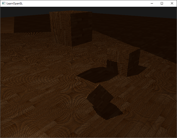
If you did things right you should indeed see (albeit with quite a few artifacts) shadows on the floor and the cubes. You can find the source code of the demo application here.
Improving shadow maps
We managed to get the basics of shadow mapping working, but as you can see there are still a few artifacts related to shadow mapping that we'd like to fix for better results, which we'll focus on in the next sections.
---------------------------------------------------_________________________________
No comments:
Post a Comment